Continue to Site

Eng-Tips is the largest engineering community on the Internet

Intelligent Work Forums for Engineering Professionals

  • Congratulations cowski on being selected by the Eng-Tips community for having the most helpful posts in the forums last week. Way to Go!

HELP on Modelling!!

Status
Not open for further replies.

sushi75

New member
Mar 11, 2015
84
Morning All!

I'm currently trying to build a model with Femap, and I'm struggling a lot, I've spent hours and hours to get something but I'm still at square one :-((

I've got a tank model, so the profile has an parabolic shape. At the moment it is made of shell elements, and what I want to do is to create a thicken part on the top which will then be meshed with solid elements.

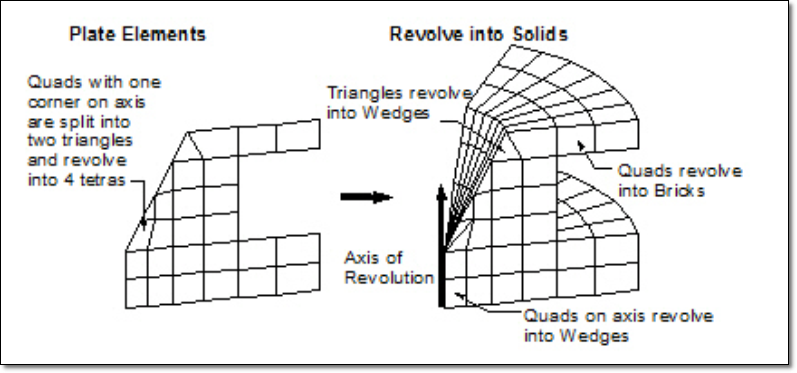
So from the profile, I want to thicken the part in a tapered way. Then I can mesh and rotate the elements to complete the job.

But I cannot find a way to do that!! I cannot simply offset the profile as the thicken part should be tapered. It's all about creating a surface at the end but I cannot find a way forward.

I've included a screenshot of the original profile made of shell, so you can have a better idea.

There are a lot of femap experts here, so I hope someone can bring me some clarifications or bright idea!!

Any help will be much appreciated.

In advance, thanks a lot!

Cheers,

T
 
 http://files.engineering.com/getfile.aspx?folder=6ce06352-d913-4360-9b89-c82f502966cb&file=profile.png
Replies continue below

Recommended for you

Dear Tom,
i don't understand very well your problem, things in FEMAP are very easy!!. Post an sketch of your tank to realize how is the geometry. Do you have the tank geometry created in 3-D in any CAD format?.
Best regards,
Blas.

~~~~~~~~~~~~~~~~~~~~~~
Blas Molero Hidalgo
Ingeniero Industrial
Director

IBERISA
48004 BILBAO (SPAIN)
WEB: Blog de FEMAP & NX Nastran:
 
Hi Blas,


Thank you so much for your reply. I agree, modelling in femap is easy that's why I don't blame the software but myself for not managing to build my model!

I have included a picture of the situation.

The full model is a tank, thus axisymetric, made of shell elements. The idea is to grow the upper part (which was shown in the first message, I used a clipping plane to only show the area of concern), and to make this part thicker, sort of reinforced if you prefer. It is intented to be be made of solid elements. These will be then connected to the shell elements of the remaining structure via RSSCON.

But first thing first, how to create this profile?

Then I guess I can mesh it, and then revolve the elements around the axis creating the solid ones.

Hope this is now a bit more clear. If not let me know.

Thanks a lot,

t
 
 http://files.engineering.com/getfile.aspx?folder=6c06aca6-731d-4669-9c93-7c10a8d46cf6&file=MODELé.png
Dear Tom,
Simply create a 2-D surface in one quadrant, mesh it with 2-D plane elements (of type plot-only, not need any property) and rotate using command Mesh > Revolve > Elements. Better first define solid geometry to associate later the mesh with the 3-D solid geometry using Modify > Associativity > Automatic, this way you can apply loads & BCs to the geometry, not to the mesh.

mesh-revolve-elements_yx3yjk.png


The rigid joint between Shell & Solid mesh can be done using GLUE EDGE-TO-FACE, forgot at all RSSCON command, the key is to have geometry.

Best regards,
Blas.

~~~~~~~~~~~~~~~~~~~~~~
Blas Molero Hidalgo
Ingeniero Industrial
Director

IBERISA
48004 BILBAO (SPAIN)
WEB: Blog de FEMAP & NX Nastran:
 
Hi Blas,

Thanks for your support, it definitely helps. I got the point about the generation of solid elements from the illustration.

What I'm struggling with at the moment it the previous stage, namely the creation of the profile. I need to create a profile surface, and I don't find a way to do it. Is it based on spline (seems too complicated)?
if you open the previous attachment you can see the type of geometry I try to create. But I'm sort of drowning with this surface creation!

I can first define a curve based on the nodes of the tank profile, and ideally I could offset it a "non_constant" value to represent the decrease of thickness as depicted in my previous thread.

There might be an easy way to do that, but I've not found it yet!! ny suggestions would be more that welcome :)

Cheers,

t
 
as I understand it you have a 2D element mesh, presumably the elements are on the OML but maybe the mid thickness surface.

can you create the OML and IML surfaces ? with these you should be able to create a 3D geometry volume and this is something you can mesh. the trick is joining the two at their interface.

another day in paradise, or is paradise one day closer ?
 
another thought, to save creating new OML and IML surfaces, you may be able to extrude the existing surface to create a 3D geometry volume.

another day in paradise, or is paradise one day closer ?
 
Hello!

Thanks for all your replies. I managed to progress on the issue further to your comments. The only way I found to create the profiled surface was by creating points which I lacated by hand. A bit a pain, but I could at least get a result.

Regarding the OML and IML surfaces, I'm not aware of these kind of geometry. rb1957, could you give a bit more details about that? I guess it could be useful and may be a possible way forward for the problem I'm currently working on.

Cheers!!

T
 
your 2D surface is some plane of your real shell ... probably mid-thickness. "OML" is outer mold line or the outer surface of your 3D plate; "IML" is inner. if your shell is designed in CAD, you should be able to import the CAD model into your FEA. or you can create new surfaces, off-set from the existing surface to match the outer and inner faces of your shell.

I liked the misspelling "lacated", and of course "lacated by hand" raised a chuckle.

another day in paradise, or is paradise one day closer ?
 
Status
Not open for further replies.

Part and Inventory Search

Sponsor