Continue to Site

Eng-Tips is the largest engineering community on the Internet

Intelligent Work Forums for Engineering Professionals

  • Congratulations cowski on being selected by the Eng-Tips community for having the most helpful posts in the forums last week. Way to Go!

Hello, friends! According to WRC-4

Status
Not open for further replies.

Sajjad2164

Mechanical
Dec 22, 2015
55
Hello, friends!
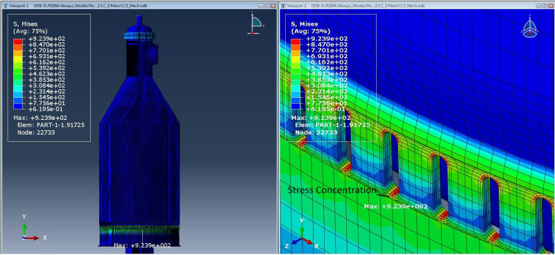
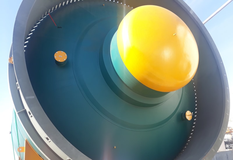
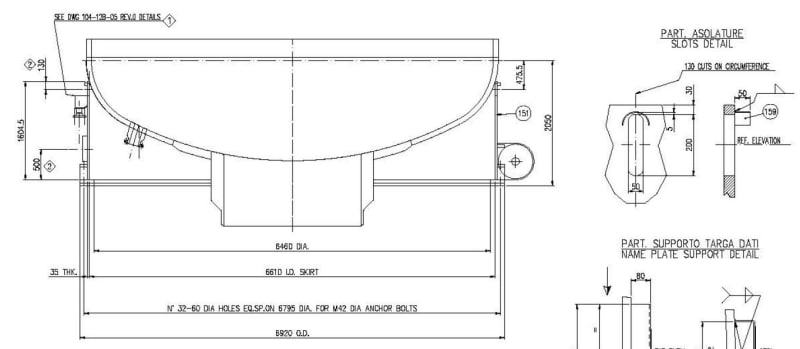
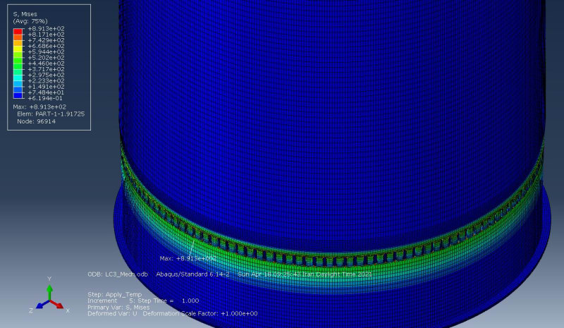
According to WRC-470, when we have a high temperature in the vessel, there are some methods to reduce the stress level occurring in the skirt-to-head junction including hot-box configuration and using slots to make the region more flexible. I am modeling a vessel on which the designer has put several slots to overcome the high level of thermal stresses. I've encountered a high level of stress concentration. Does anyone have any idea what I should do?
Thanks
Capture_kg76u5.jpg
 
Replies continue below

Recommended for you

I take it that this is a coke drum?
 
No, it's not a coke drum. It's a secondary reformer. I'm looking forward to a special consideration that gives the analyst the permission to neglect stress concentrations happening at the crown of the notch of the slots.
Capture_edxacv.jpg
 
There are high stresses there. That cannot be escaped. You have to deal with the fatigue implications of that.

I don't understand why or how you want to "neglect" these stresses. What failure mode are you considering?
 
There isn't any special consideration, you have to design it for fatigue. Usually these are the limiting locations, and cracking from the slot or keyhole is common. It might be worth assessing how effective the slots actually are and whether you really need them. By inspection the design could be improved, has it already been constructed?

As TGS4 suggested, this is common for coke drum designs. You could start by looking in to some of the more recent ASME publications and the code drum design guides available.
 
Dear TGS4, I am struggling to pass the linear elastic analysis criteria. I considered the thermal stresses occurring in the vessel as secondary stresses and the criterion to be passed is 3 times the allowable strength of the material (SA-387). I've attached an image of what I'm trying to do in this project. Should I conduct a fatigue analysis even if we have the same equipment working in a petrochemical plant without any problem?
Capture_cndarr.jpg

Dear BJI, the vessel is built a couple of years ago, and it's working quite normally now.
When I extract the stress linearization results in the SCL's at the skirt-to-head junction, I get the membrane plus bending passed but the local failure criteria are not passed.
Capture_wk4ndp.jpg
 
Can you explain what you are trying to achieve by the analysis if the vessel is already in service? You likely shouldn't need to evaluate local failure, unless the original design was based on DBA (unlikely) or there was some degradation that requires FFS. If necessary you could use the elastic-plastic procedure. Are the stresses linearized or do these values include peak stress at locations 1 and 2 on the SCL?

It is very likely this vessel would have been better without any slots. Do you have access to the original design calculations?
 
Thank.
[ul]
[li][/li]
[/ul]We are going to manufacture the equipment for another petrochemical company, and they asked for the FEA calculation too. That's why I'm struggling with the finite element process. The FEA calculations of the previous project had been done in a simplified way, in which they didn't see many details when they were modeling the equipment, so the owner wants us to perform a more comprehensive calculation. Moreover, the existing equipment has shown that the temperature goes high in the cone to shell junction, therefore they want us to make sure they shouldn't think about any specific consideration in the mentioned area.
[ul]
[li][/li]
[/ul]The design is based on DBR (Design By Rules).
[ul]
[li][/li]
[/ul]I got the local failure results after linearizing between two points locating at either side of the shell.
[ul]
[li][/li]
[/ul]I have access to the original design calculations
 
I understand now. For DBR you do not need to perform additional local failure assessment. Check it for yourself with the EP procedure if you are unsure that it is acceptable. If the slots were excluded for the new design, the bending stress in the top of the skirt would be the limiting location under thermal loading. Check it for ratcheting and fatigue. I would guess that ratcheting would not eventuate with low primary membrane stress in this region, but you could be in the cyclic plasticity range. Not sure if the modified structural stress method (structural strain) would be considered code compliant but the EP fatigue method is included in part 5.

Probably best to assume the hot box is inefficient and design for the worst case. Unless you have temperature data from the vessel in operation, then this could be used to calibrate your model.
 
Dear BJI, I'm wondering on what basis you are saying I don't need to perform an additional local failure assessment for DBR. I mean is there any note in ASME which I can refer to?
Thanks
 
Read the overview for local failure assessment. Think it might be under 5.3.1 but don't have a copy of the code in front of me. For reference, there is some supporting criteria in API579.
 
Sajjad2164 said:
Should I conduct a fatigue analysis even if we have the same equipment working in a petrochemical plant without any problem?
Do you understand that fatigue is a time-based failure mechanism? It may take 20-25 years to see problems.

There is nothing DBR about those slots. This is absolutely a DBA design. You said earlier that you are struggling to pass the linear elastic stress criteria. However, that's not what I asked about. I specifically asked you to focus on the failure modes. It looks like you are focusing on the ratcheting failure mode, and perhaps the local failure mode. I suspect that you are performing the local failure check incorrectly.
 
In accordance with the following note in ASME, I am wondering whether the fatigue analysis is needed or not.
Capture_sk1ju5.jpg

The thickness configuration of the vessel is based on DBR, but those slots are based on the recommendations of WRC-470 as a way to control extra thermal stresses in the area. At first, I modeled the vessel with a hot-box and the thermal stresses were dissipated from the skirt-to-head junction.
I've passed the plastic collapse criteria (ELASTIC STRESS ANALYSIS METHOD) but the owner wants me to check the local failure as well. According to the above conversation, and as @DJI mentioned I don't need to check for local failure.
 
You will not find the details that you have as a "standard design detail" that would exempt you from performing the Local Failure check. Plus, if the owner wants it, and they are paying for it, then you ought to be doing it.

I would not exempt this using 5.5.2.2. You don't have long enough experience.
 
@TGS4, I'm not looking forward to any details to help me exempt local failure check, but I'm looking forward to finding the best criterion because I believe when we have 400 degrees of centigrade in the vessel with a very complex geometry, it's not accurate to use elastic local failure procedure. Instead, I assume that elastic-plastic local failure analysis will give me better results in the mentioned condition. Please guide me if there is any note in the code which let you go to the other criterion of local failure (Elastic-Plastic) when the hard situation like my case is about to be checked.
You guessed right!
I don't have enough experience in this field, and that's why I'm here trying to use other's experiences.
 
Either method is acceptable according to the Code. If, as the User, you would prefer only the EP method be used, you are able to require that.
 
Was it failing before you introduced the slots? My recommendation was to try and removed the slots, this would be DBR for the head to skirt junction. If your client is requesting the local failure assessment then it is easy enough to include, required or not.

If the slots were sufficiently removed from the skirt to head junction, then this would also follow DBR. I only saw linearization descriptions for this location, not the slots specifically. WRC-470 specifies separation of the slot from the skirt to head junction, which doesn't appear in the example supplied. The thickness of the skirt, relative to the length of the slot, makes me question how effective they actually are. Quite likely, the reduced fatigue life caused by the addition of the slot may be more detrimental to the vessel integrity than excluding the slots. Coke drum slots crack and get weld repaired frequently. Assess the actual failure mechanisms and optimise the design accordingly.
 
I'm not in a position to remove the slots. I can just suggest it. At first, we didn't notice slots in the skirt. We modeled the vessel without slots and the high temperature in some load combinations caused a very high level of secondary stress and the criteria were not met. After that, we modeled a hot-box for the vessel and the secondary stresses were significantly decreased. The owner gave us a new plan in which there were 130 slots near the skirt-to-head junction. We assumed these slots are definitely meant for reducing the stresses and removed the hot-box configuration. If the slots were remote from the skirt-to-head junction, I believe they wouldn't be functional.
%DB%B2%DB%B0%DB%B1%DB%B9%DB%B0%DB%B2%DB%B1%DB%B3_%DB%B1%DB%B5%DB%B1%DB%B0%DB%B0%DB%B1_pardl0.jpg

Capture_rydeec.jpg
 
I have another question:
I'm wondering if the highlighted text in the image means that we are not allowed to use "Elastic Analysis – Triaxial Stress Limit" in operating conditions
Capture1_gaqxqa.jpg
?
 
We modeled the vessel without slots and the high temperature in some load combinations caused a very high level of secondary stress and the criteria were not met.

Typically in the skirt you will have high secondary bending stress but low primary stress. IMO for ratcheting to be likely, you need to have a reasonable sustained primary stress in combination with your cyclic thermal stresses. Therefore, if you can't ratchet, it will either shake down to elastic fatigue or result in cyclic plasticity, both of which can be addressed. In the absence of high stresses without thermal, your secondary stress can be reasonably high, if the appropriate analysis is performed. Were you running refractory failure cases that caused the exceedance?

After that, we modeled a hot-box for the vessel and the secondary stresses were significantly decreased.
The HB can be used in conjunction with slots. Out of interest, how did you model the HB? What certainty do you have of the actual efficiency relative to the analysis performed?

The owner gave us a new plan in which there were 130 slots near the skirt-to-head junction. We assumed these slots are definitely meant for reducing the stresses and removed the hot-box configuration. If the slots were remote from the skirt-to-head junction, I believe they wouldn't be functional.
That is what the slots are intended for. The design isn't actually as simple as just adding slots near the skirt junction. There are lots of factors that influence the design, and there has been significant research in the area. As I mentioned, you should search for some of the publications on this topic. I wasn't saying you need to remove the slots, only presenting another option to consider since you had the ability to redesign the vessel. If it is what the client wants then go with it. However, the 'advantage' of using slots in high cyclic thermal applications is offset by the introduction of fatigue initiation locations. Aside from the design perspective of the slot location relative to the head, which is another discussion, the distance for crack propagation is decrease if you have the slots right at the head junction.

The local failure assessment is actually the trivial assessment for this design. To answer your question, you are allowed to use elastic analysis, what specifically gives you reason to question it? Maybe if you refer to the EP load combination for the local failure criteria in Table 5.5 it might clear this up. Were the stresses in the table you posted actually 'primary' principal stresses?

 
Status
Not open for further replies.

Part and Inventory Search

Sponsor