advidana
Electrical
- Dec 24, 2002
- 433
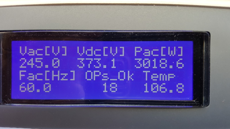
The Grid tie solar system a house was design to be overdriven for maximum continuous solar power during daylight cycle. The utility is 120/240 VAC single phase system 200 amp service. It has a 76kw SE7600-US Solaredge inverter with 28 Solaredge P320 power optimizers mounted externally on the side of the house adjacent to the meter. Each optimizer has a 300 watt Q-peak G4 solar panel (module) connect in parallel to it mounted on the roof facing east with no obstructions. The optimizers are suppose to be connected in three strings 9-9-10. The three strings are connected in a j box on the roof and run in EMT with # 8 cu wire to the inverter about 25 feet away. The workmanship and code compliance of the installation is excellent. The system works is producing 5250 watts at 240 VAC 60 HZ output. The inverter had a monitor reading display of 240 VAC-247 VDC-5250 PAC was taken at the installer about 2 pm in September on a cloudless day in southern Nevada.
The inverter is presently turned off waiting for the utility to connect their meters used for solar power. I will be monitoring it closely once the inverter power is on. With the power off the optimizer produce a safe power of 1 volt DC each. With the invertor off- The input voltage to the inverter input terminals is 13.03 volts DC.
My concern is that the Dc voltage is low at 246 VDC- it is suppose to be a constant 360 VDC. Per vendor specification-This 360 DC volt will be maintained if the string optimizers are connected in series string length a minimum of 8 to a maximum of 25. The inverter nameplate voltage operating voltage range is 270 -500 VDC.
The Electrical contactor who installed the system claims that some lower voltages are normal for this systems and that the Dc voltage reading was read in error by his technician that installed the system-That appears reasonable to me based on his experience. He claims the voltage would be 288 VDC from the strings in parallel. the lowest string 9 string would clamp the voltage to it voltage output of 288 VDC and projected amperes of 29.1 based of full peak wattage of 86400 from solar panels . He also said the current would increase to compensate for the lower voltage to maintain normal solar power output-also reasonable. His logic is coorrect for solar panels strings without optimizers. I have read on the internet that this is also normal for other manufactures optimizers and inverter.
I called the hot line from the manufacture twice- one reprehensive claimed the some of the optimizers could be connected backward causing reverse polarity problem's and he said that if a string was less that 8 the optimizer that string would shut off. The other representative claimed that the system was overdriven to high causing the lower voltage and was not cause by reverse polarity. They both thought the contractor was mistaken.
I don't have practical experience with this type of solar system. The inverters maximum input current is 23 amps and has short circuit protection of 45 amps so the # 8 copper stranded feeder from the roof are protected. I don't know if the input is current limited or it is some value of a Time Current curve for a current limiting fuse or breaker.
Is this normal or is there a problem to be concerned with.