Continue to Site

Eng-Tips is the largest engineering community on the Internet

Intelligent Work Forums for Engineering Professionals

  • Congratulations cowski on being selected by the Eng-Tips community for having the most helpful posts in the forums last week. Way to Go!

GFCI and chassis ground 1

Status
Not open for further replies.

zappedagain

Electrical
Jul 19, 2005
1,074
A colleague recently inherited a project where ground and chassis ground got intermingled on the secondary of the power supply long ago, so several hundred sensors are basically wired to chassis ground. While this works (surprisingly, to me), they've now found that when they plug into a GFCI (Ground Fault Circuit Interrupter) the sensor currents can trip the GFCI as the primary side of the power supply has chassis ground wired to earth ground.

Are there any safe ways to make this circuit work with a GFCI, other than rewiring the sensors? Maybe resistive coupling between the chassis and earth ground? A 60 Hz bandstop filter to earth ground (via the GFCI)?

Z
 
Replies continue below

Recommended for you

Isolating transformer?

CR

"As iron sharpens iron, so one person sharpens another." [Proverbs 27:17, NIV]
 
How can I do that without floating the chassis? He's looking to avoid potentially unsafe situations as he has a multitude of scientist wiring and unwiring different projects into this large project. If someone wires the hot wire to the chassis that could be bad.

Z
 
What do you mean ground and chassis ground? Are the 4 wires going to each box? If so the GFCI is intended to detect differential current between line and neutral, so how is it possible to detect anything that doesn't involve line and neutral?
 
The differential current is the "anything that doesn't involve the line and the neutral".

Bill
--------------------
"Why not the best?"
Jimmy Carter
 
What I meant was - if (I mentioned 4 wires) there are two different ground paths and there is no connection between line, neutral, and those grounds the GFCI should not be triggered.

It was meant as an exercise for the OP to figure out where their misunderstanding of the situation lies, not as a primer on how to wire an electrical system.
 
I understood that most (all?) GFCIs worked by directly measuring the difference in currents in the Hot and Neutral wires, using a current-sensing core wired appropriately. When the Hot current leaks to Ground (a Ground Fault), then the Neutral current no longer balances the Hot, and when the difference (between Hot and Neutral) reaches the trigger point (say 5mA), then it opens the circuit.

Point being, if you have foreign currents (from distant sensors) arriving on the Chassis Ground, then that in itself shouldn't affect your local Hot or Neutral currents. Neither Hot nor Neutral should be connected to Chassis Ground within the chassis, so Ground currents should not affect either of them. (Ground and Neutral should of course only be connected at the Electrical Panel.)

By way of example, if you took another AC Hot wire (from an entirely different circuit) and contacted it directly to your local Chassis, then the overload should pop the breaker or any GFCI on that other circuit. The local GFCI shouldn't directly notice the excess Ground current.

Now if you have very large Ground currents (arriving from the distant sensors), then they might induce currents in the local Hot and Neutral wires due to wiring proximity (e.g. in the power wiring, within the chassis, within the power cord, or within the wall).

So perhaps you should measure the Ground currents to see what's going on with each sensor circuit.

Acknowledge in advance that I may have misunderstood. Clarifications and correction welcome. :)

 
VE1BLL - That makes a lot more sense that the GFCI is measuring the difference between hot and neutral. Another piece of data is that this seems to be related to the power supply generating the 'SELV' on the secondary. Maybe it is really a power factor issue or something tripping the GFCI as the problem seems to be related to 'cheap' power supplies.

3DDave - Instead of 'ground' I should have said the return line for the SELV. The circuit has the SELV return and the chassis ground tied together. The chassis ground is tied to the main ground of the 3-wire plug.

Thanks all!

Z
 
Z said:
...the problem seems to be related to 'cheap' power supplies.

Check those for leakage or "illegal" connection between Neutral and Ground.

Obviously if Ground and Neutral get connected within the chassis (perhaps due to a cheap badly-designed power supply) then the Neutral current (required to balance the Hot current in the GFCI) would be partially diverted to the Ground wire, and could thus trip the GFCI.

If there are capacitors between the Neutral and Ground within the power supplies, combined with some higher frequency noise arriving from the sensor wiring, then it might couple onto the Neutral. Seems unlikely, but unusual faults are often from what would be unlikely.

I'd recommend that you 'have a chat' with your sensor wiring. See what your 'uninvited guests' look like. Disconnect and measure O/C voltage, and then insert a current meter in series to ground. Start with AC, but check DC too. Start carefully (with caution) just in case.

Finally, suspect the GFCI itself. Maybe it's gone bad.

 
Is your power supply putting out any high frequency ripple?
It doesn't take many feet of conductor for the capacitive leakage from high frequency to trip a GFCI.
I was trying to use the feed through feature of a GFCI to feed a couple of standard receptacles.
The system was fed from an old stepped square wave inverter. More than about eight or ten feet of conductor to the second receptacle would cause the GFCI to trip due to capacitive current to ground.
Also, if your equipment is wired in such a way that the neutral and ground are in parallel, you will have current sharing between the neutral and ground path and can expect GFCI tripping.

Bill
--------------------
"Why not the best?"
Jimmy Carter
 
I am assuming this power supply and sensors go back to an enclosure. I would focus on the ground bar and check all the wires being tight and the terminals have bare wire under them. Usually 95% of problems that I see is pinched insulation on a wire in a terminal. This would be an indication that wires are loose on the ground and neutral side in this enclosure. Also check the neutral and ground are not loose at the control transformer. This would also cause the GFCI problem. What I am pointing out is the neutral and ground need to be properly terminated at this transformer. Otherwise you would see weird voltage measurements and floating chassiss, etc...
 
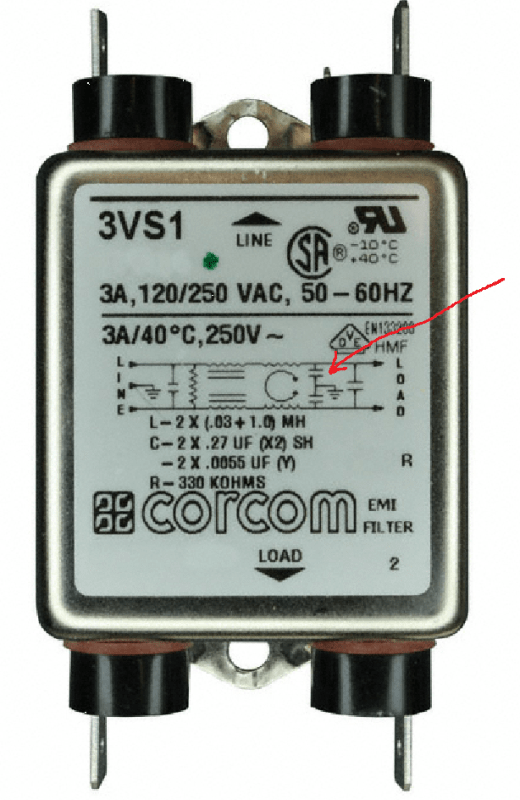
Switching supplies in a quest to remain within conducted noise limits often have front-end filters. Lots of them include capacitors to the chassis.

I had a new S-100 computer that had one of those "metal box" filters with the four leads directly hooked to the IEC computer power-cord receptacle and a fifth grounding lug tying it to the chassis. I used it to run AutoCad 4 in DOS, of course. (yeah, yeah, I date myself) One day I wore shorts and my knee bumped the 19" 6U case edge. I was jolted so hard I swept my keyboard off the desk. My office mate looked at me inquiringly. Smug bast*rd had a new Kaypro. Anyway, troubleshooting I found that the cord failed to connect the ground to the chassis and that the filter was leaking badly to the chassis making it... lively.

CORCOM_o2uckz.png


The point of the story is that frequently I find supplies that will trip GFIs. Lots of VFDs will do it too. If your system has filters, a leaky supply, or several supplies that wouldn't individually trip a GFI but en-mass their individual filters could be adding up to your GFI tripping.

Keith Cress
kcress -
 
The puzzle grows. Now I find out it is mains -> GFCI -> UPS -> multiple switching power supplies/computers, etc -> secondary returns and chassis ground tied together.

For now I told him to try an isolation transformer between the GFCI and the UPS to see if that restores the balance on the mains. I'll let you know how that works after he tries it.

Z
 
Maybe you just need to simulate someone getting a shock and then use the H$S as an excuse to force the rewiring of this system.
Sooner or later someone will tie hot to the wrong side and if they don't shock someone they could fry a lot of equipment.

In the old days the floating ground on oscilloscopes was a real risk, brushing against one with a 2kV source was very 'enlightening'.

= = = = = = = = = = = = = = = = = = = =
P.E. Metallurgy, Plymouth Tube
 
Status
Not open for further replies.

Part and Inventory Search

Sponsor