Continue to Site

Eng-Tips is the largest engineering community on the Internet

Intelligent Work Forums for Engineering Professionals

  • Congratulations cowski on being selected by the Eng-Tips community for having the most helpful posts in the forums last week. Way to Go!

Freestanding grain bins - sliding failure 1

Status
Not open for further replies.

LandyEng

Structural
Jan 19, 2017
5
Hi guys,

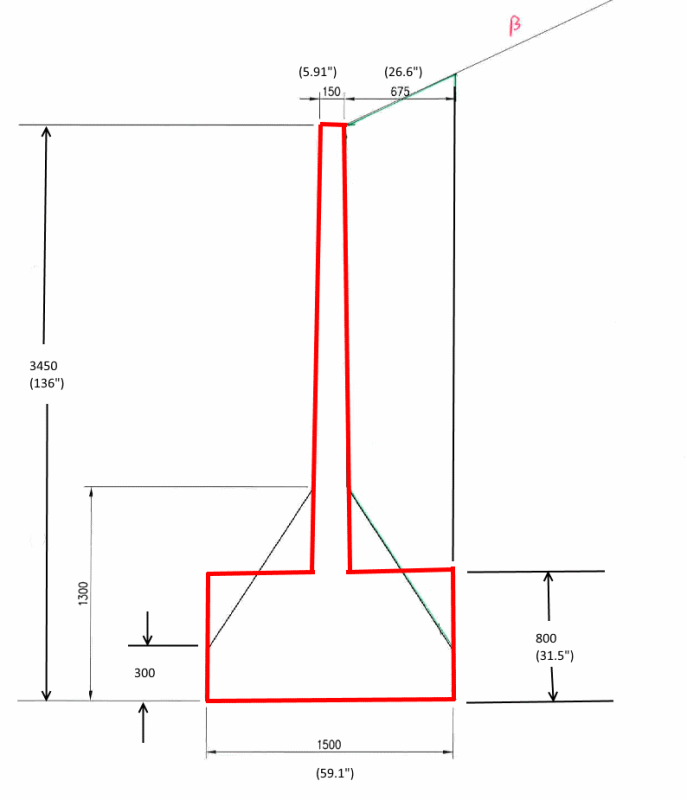
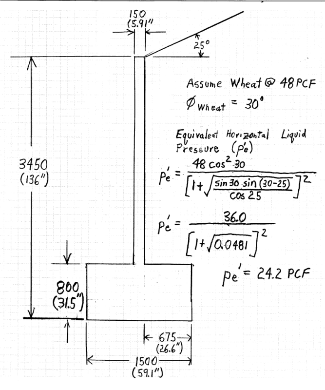
I've been looking at designs for precast storage bins for grain structures with various heights and base widths. There will be many of these manufactured so weight and material use is a key priority, however I'm getting blown out of the water with failure by sliding. These particular bins are intended to be lifted via forklifts and are simply sitting on a concrete slab. They should be able to retain with material on a single side only, but may have material on both sides (wouldn't be an issue).

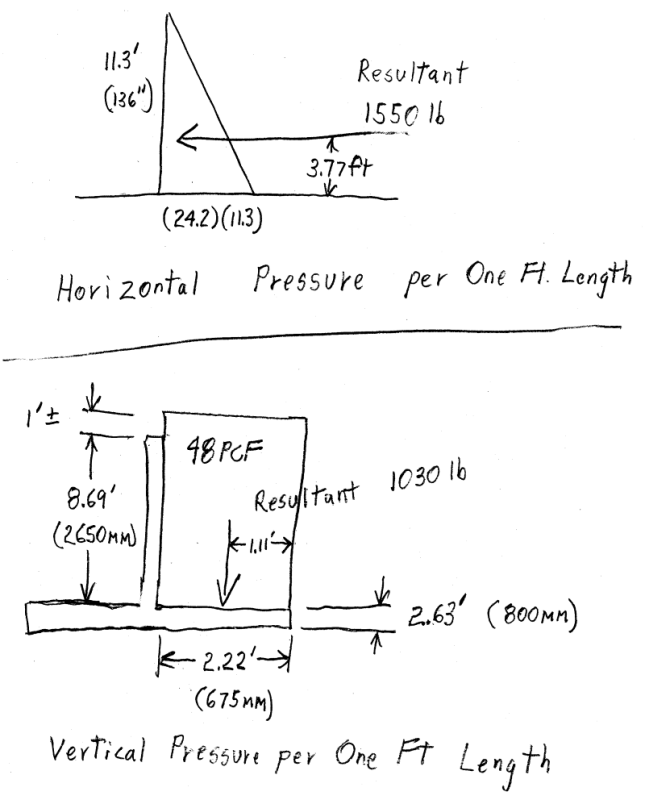
Using Rankine/Coulomb methods, I have proven overturning working for 4.32t, but sliding is taking me to 8.33t. This is compared to 3.85t from others with similar options, but I simply cannot see how they could prove sliding to work.

Are there any assumptions to be made on friction? I have been using (Mass of block + Vertical weight of grain on wall) x Coefficient of friction must be > than Total lateral force generated by grain.

Really hope I'm not missing something obvious!
 
Replies continue below

Recommended for you

A sketch showing your assumptions will help.

Do your calcs represent static conditions or grain placement activity? I don't know much about grain storage, but this paper seems to indicates that "vertical weight of grain on wall" applies only during filling operations... not at steady state.

[idea]
[r2d2]
 
Model of the wall attached. As mentioned these are designed to be 'portable' - lifted by forklifts and placed on concrete wherever necessary. Thank you for the link, SRE, I have had a quick read, however this seems to discuss cylindrical loading moreso than my situation (a "retaining wall").

The angles in the drawing are as follows:

β - angle of backfill - 25°
ϕgrain - angle of repose of grain - 30°
α - slope of proposed retaining surface - I've simplified this as a line from the base to the top to get a uniform angle of 101°
δ - angle of resultant force - 24.5°
Ka - as per page 9 of this publication: [URL unfurl="true"]http://www.civil.utah.edu/~bartlett/CVEEN6920/Earth%20Pressure%20Theory.pdf[/url] - 0.675


The resultant force therefore acting at δ is 49.6 kN per metre (=0.5*H2*Ka*12) where grain density is 12 kN/m3 and height is 3.5 m.

Resolving this into horizontal and vertical components gives me 40.4 kN per metre horizontal and 28.8 kN per metre vertical. Using a factor of 1.25 on this and a factor of 0.8 on the weight counteracting, it would be:

1.25 x 40.4 = 0.8 x [(Mblock + Wsoil) x μ]

Where Wsoil is the amount of soil I'm willing to assume aids in vertical mass and μ is the coefficient of friction between concrete and concrete - I've taken 0.4 as my limit.

I hope that can clarify my problem enough.
 
LandyEng - Thanks, now I understand where how the "vertical weight of grain" applies.

I've never been good at developing equations, so have taken the following steps:

1. Made some estimates of missing dimensions.
2. Transformed the partition's geometry into an approximate equivalent with only vertical and horizontal surfaces.
3. Assumed a unit weight for the grain (per AISC, bulk wheat @ 48 PCF).
4. Metric and I don't get along, so have made the conversion and calculated forces using numbers.
5. Used Rankine-Coulomb Equivalent Horizontal Fluid Pressure for an inclined bank. See pages 5 and 6 of US Steel Steel Sheet Piling Extracts on my website.

Here are my assumptions and calcs. Have also attached the same pages in .pdf format.

OP_Diagram-1_rmx530.png


Equvalent_Bin_-_1-800_tkdjyi.png


Equvalent_Bin_-_2-800_ns1oh2.png


[idea]
[r2d2]
 
Thank you for the link and detailed response. I've gone through (and even attempted to use imperial) but I'm still getting caught in a similar position. The theory in your extract gives me a final horizontal force of 37.1kN per metre (2545 pounds per foot)

Using a coefficient of friction of 0.4 and solving as follows:

37.1 = μ (Mvert)
Therefore the total vertical mass to resist 37.1kN per metre of sliding must be 37.1/0.4 = 92.8kN per metre
If I perhaps conservatively assume the vertical mass of soil to be 0.675m x 3.5m x 12kN/m3 x 1m = 28.4kN per metre
The block then has to weigh 92.8 - 28.4 kN per metre ===> 6.55 tonnes per metre of block

This isn't even using any factors of safety - I had been trying with 1.25 x 37.1 and 0.8 x Mvert. Working this through gave 11.6 tonnes per metre, way way way over what others have supposedly proven (3.85 tonnes per metre).

I have hand calcs of my steps above however won't have access to a scanner until tomorrow. Am I missing something with my analysis of sliding?
 
LandyEng - I worked with the numbers, too. Concur that sliding is a problem. IMHO, the design dimensions are out of proportion. It does not have enough "heel" compared to the the height of the stem. A longer heal would give more total load (from the weight of the grain) for the friction force. Also, this would allow the concrete weigh to be lower. The design seems heavy for forklifts... 2580 lb/ft by my calcs.

URL]


See these bins for comparison:

URL]


[idea]
[r2d2]
 
Exactly, SRE. My suggestions at increasing the base width or adjusting the shape were met with similar responses each time... "how have these other companies proved it?"

One such company sells:
An 'A' shape 3.05 m high
1.22 m wide base
2.75 tonnes per block
Can apparently retain 16 kN/m3 gravel/sand at a backfill slope of 25° !?

they quote "additional stability generated by the frictional force down the face of the wall." and "To assist in the spread of load horizontally the units are normally fixed together with a steel plate, which also provides a seal to the joints."

Their 3.65 m block has the same 1.22 m wide base and only weighs 2.85 tonnes. Has anyone else got any insight into how this could work?
 
LandyEng said:
Their 3.65 m block has the same 1.22 m wide base and only weighs 2.85 tonnes. ...any insight into how this could work?

Yes, by anchoring the block to the concrete slab it sits on. See page 9 of the brochure.

For other "tests", without anchors, the competitor appears to take a short length of wall, lock it to perpendicular sections for additional ballast, then put a minimal (reverse) sloped loading on the "tested" wall:

URL]


Your assumed loading conditions are for an "infinite" length, with worst-case loading conditions. For what it's worth, I agree with you. That is the correct way to make the calcs. For comparison, why not examine the exact design, with no anchors, using your assumptions. I'll bet performance is unacceptable, also.

[idea]
[r2d2]
 
Yes, the anchoring is obviously the catch with the larger module. I guess I'm going to have to resign to the fact that my analysis was correct but there are just certain assumptions/conditions as to the installation and use of the modules. As you said, I don't think anyone could prove these as 'standalone, infinite length' systems given the outputs we were getting.

Cheers for your input, SRE.
 
You already have help with the numbers; I just have some observations and cautions:

These units are way too narrow to retain soil. Free-standing gravity or cantilever walls commonly have base-width to height ratios between 0.5 and 0.7. The brochure shows a limit of half-height backfill for granular soil. Grain is much lighter, and that does make a difference.

The grain storage business has been highly competitive and poorly regulated. Builders have been innovative since I was doing geotech for various kinds of grain storage structures in the 70s. There have been a lot of failures, some of which caused fatalities. Don't assume that someone else's design is sound. He may be a defendant next season.

It would be easy for a customer to abuse these units. During a rush to handle a bumper crop, someone will arrange them in a big square and fill it to the angle of repose until the grain runs over the edges. The lateral pressure goes up fast as the slope approaches the angle of repose.

And then there is the second owner who may have an entirely different material to store. You may want to consider painting some cautions on the product.

Good luck.
 
Status
Not open for further replies.

Part and Inventory Search

Sponsor