dauwerda
Structural
- Sep 2, 2015
- 1,045
AISC Design Guide 24 presents a connection design example of a beam over HSS column connection (Example 4.1 in section 4.5). My question is: Would there be any change in the cap plate design (thickness determined to eliminate prying) if the cap plate has a center hole cut out to allow for galvanizing, and if so, what would that be?
In the example, the HSS column is a HSS 8x8x1/4, so lets assume the fabricator wants to cut out a square hole that is 7"x7" so that the plate only extends inside the sidewall of the HSS 1/4" to allow for ease of galvanizing.
My thought is that this would affect the design in the following way:
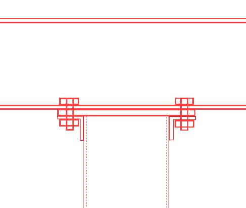
Per the discussion in section 9 of the steel manual, the prying check is based on the assumption that the flange is in double curvature. My thought is that by adding the cutout this is no longer a valid assumption as the HSS wall will yield before the plate will (See attached sketches). If this is the case, how is this handled? Would the discussion about the asymmetric loading found in the 15th edition of the manual (below) apply in this case? If so, wouldn't the "point of application of the load" still just be the HSS wall as it carries tension induced by the moment at the joint, which wouldn't change the design?
The 15th edition of the manual includes the following discussion about the dimensions b and b': "These values are valid for tees and angles if the load is delivered symmetrically and the angle shown represents one of a pair of back-to-back angles. When the angles are not back-to-back and connected to a relatively flexible support, the effective eccentricity may be increased and a distance measured to the heel of the angle or possibly somewhat larger might be warranted. It is common to assume there is no moment transfer between the flange and the element to which it is attached, that is, all of the moment required for equilibrium of the flange is assumed to be taken at the bolt line. This discussion is not intended to be applied to asymmetrical conditions. When the load is delivered asymmetrically, an even greater moment will result. For instance, if the angle is attached to only one flange of a wide-flange member used as a hanger and the hanger is restrained from rotating about the bolt line, then the eccentricity would be measured from the centerline of the hanger or to the point of application of the load."
Or, is my overall thought here incorrect as the tension in the wall of the HSS will prevent it from bending and the original design per the example is still valid? Or does some other failure mechanism come into play (that is not addressed in the design guide) and need to be looked at?
I apologize for the long post but would greatly appreciate any thoughts on this subject.
Thanks in advance!
In the example, the HSS column is a HSS 8x8x1/4, so lets assume the fabricator wants to cut out a square hole that is 7"x7" so that the plate only extends inside the sidewall of the HSS 1/4" to allow for ease of galvanizing.
My thought is that this would affect the design in the following way:
Per the discussion in section 9 of the steel manual, the prying check is based on the assumption that the flange is in double curvature. My thought is that by adding the cutout this is no longer a valid assumption as the HSS wall will yield before the plate will (See attached sketches). If this is the case, how is this handled? Would the discussion about the asymmetric loading found in the 15th edition of the manual (below) apply in this case? If so, wouldn't the "point of application of the load" still just be the HSS wall as it carries tension induced by the moment at the joint, which wouldn't change the design?
The 15th edition of the manual includes the following discussion about the dimensions b and b': "These values are valid for tees and angles if the load is delivered symmetrically and the angle shown represents one of a pair of back-to-back angles. When the angles are not back-to-back and connected to a relatively flexible support, the effective eccentricity may be increased and a distance measured to the heel of the angle or possibly somewhat larger might be warranted. It is common to assume there is no moment transfer between the flange and the element to which it is attached, that is, all of the moment required for equilibrium of the flange is assumed to be taken at the bolt line. This discussion is not intended to be applied to asymmetrical conditions. When the load is delivered asymmetrically, an even greater moment will result. For instance, if the angle is attached to only one flange of a wide-flange member used as a hanger and the hanger is restrained from rotating about the bolt line, then the eccentricity would be measured from the centerline of the hanger or to the point of application of the load."
Or, is my overall thought here incorrect as the tension in the wall of the HSS will prevent it from bending and the original design per the example is still valid? Or does some other failure mechanism come into play (that is not addressed in the design guide) and need to be looked at?
I apologize for the long post but would greatly appreciate any thoughts on this subject.
Thanks in advance!