Continue to Site

Eng-Tips is the largest engineering community on the Internet

Intelligent Work Forums for Engineering Professionals

  • Congratulations cowski on being selected by the Eng-Tips community for having the most helpful posts in the forums last week. Way to Go!

Datum

Status
Not open for further replies.

VD2108

Mechanical
Sep 11, 2013
7
Hi everyone,

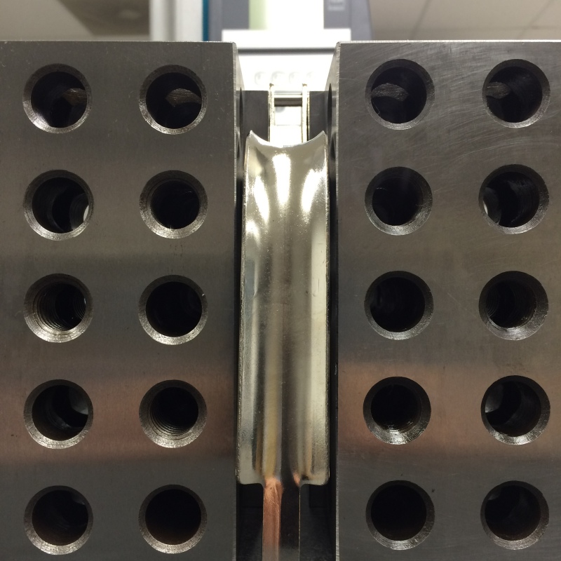
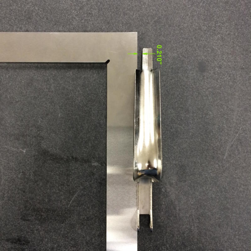
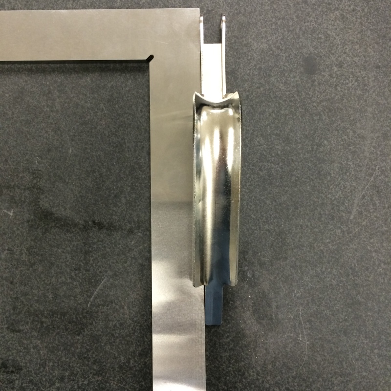
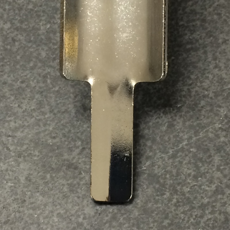
We have these triggers that are dimensioned and toleranced as shown in the attached image. Recently we have switched the supplier and received parts that are not good. The main problem is that the center of the ears (slot) does not align with center of the tab (0.43 dimension) at the bottom. The part is not straight. The goal is to have centers of slot and tab to have controllable alignment.

I am thinking to add Datum A to slot (0.416 dimension) and location/position tolerance to tab (0.43 dimension) referencing Datum A.

Am I doing this right?

Thanks,
Vadim
 
 http://files.engineering.com/getfile.aspx?folder=990affe9-6837-4e44-b540-74654b6b497c&file=Trigger_revA.JPG
Replies continue below

Recommended for you

Vadim, your file didn't attach for some reason.

What drawing standard if any do you work to, ASME Y14.5M-1994?

Posting guidelines faq731-376 (probably not aimed specifically at you)
What is Engineering anyway: faq1088-1484
 
My opinion:
The thru holes (both of them) datum feature A (primary datum)
.416 width --datum feature B (secondary datum)

Position .43 in relation to A primary and B secondary (maybe even A at MMC and B at MMC)
Profile everything else to A(MMC) and B(MMC)including the curvature.
all radii must be basic.

Disclaimer: I don't know how this part actually functions, I imagine how this might function.


I would keep dim. .415 primary

"For every expert there is an equal and opposite expert"
Arthur C. Clarke Profiles of the future

 
No doubt the first drawing was sorely insufficient. My opinion is the datum reference frame should be as follows: make the .416 and the .43 widths two separate datum features (let's say A and B) then make A-B primary. The cross hole pattern should be secondary. Pick some other feature for the tertiary and dimension accordingly.

John Acosta, GDTP Senior Level
Manufacturing Engineering Tech
SSG, U.S. Army
Taji, Iraq OIF II
 
Still go with my original answer. The bottom slot is driven not driving ( does not stop any degrees of freedom, it is clearance with the bottom frame)
[highlight #FCE94F][/highlight]
 
Hi, Vadim:

I agree with powerhound. I think it's better to make A-B as a primary. Reason is that neither A (.416 - slot) nor B (.43 - tab) is big enough to be a good primary datum.

Alex
 
The primary control of orientation of the part is the cross-holes.

The width of the slot controls the location and would be secondary.

I'm basing this on the observation that the if the holes are misaligned by a small amount to the overall shape the overall shape will end up crooked in the handle. It looks like there is plenty of clearance in the width.

A complicating factor is that the allowable tolerance for the position of the tab depends on the clearance of the pin in the other part.

An alternative is to backdrive the holes. I would make a primary datum of the an RFS with targets at the width of the tab, the width of the slot and some other location along the trigger. The secondary datum is a target along the front edge of the slot and a point on the tab. The tertiary depends - either it is along the top of the slot or a shoulder of the tab.

Then set up a positional tolerance that is the difference in diameter of the pin hole taken from the mating virtual diameter of the clearance hole.
 
3DDave said:
The primary control of orientation of the part is the cross-holes.

Functionally you engage the slot first and insert pin thru cross-holes second.

Just like in any text book - flat surface primary, hole thru flat surface secondary.

"For every expert there is an equal and opposite expert"
Arthur C. Clarke Profiles of the future

 
Probably is six of one half a dozen of the other.......

Holes (at RFS) primary and slot (at MMC secondary)
versus
Slot (MMC) primary and holes (RFS)

I agree with Dave that to reduce the variation the holes should be RFS.

I still consider that the A-B compound is not the way to go in this case, but I could be wrong. Again, my opinion.
(.430 slot does not stop any degrees of freedom and not suppose to rub against the frame therefore not arresting any DOF's)

 
Additional information to my original post. I got these images from QC. Hopefully this helps understanding the problem we are facing with these parts.

Trigger_leveled_qsvcnu.jpg

In this image the trigger is supported by pin that is sitting on both blocks.

Trigger_alignment_2side_nf43gg.jpg

When aligning the trigger from this side, the gap is larger than what it supposed to be.

Trigger_alignment_1side_jbadxt.jpg

When aligning the trigger from the other side, there is no gap. That's what causing the rubbing against the frame (one of the support legs in the casting), when assembled.
 
This is a perfect case study to show how improperly defining a part can result in unusable parts that you still have to buy. I don't think anything about this part violates the print, does it?

"Using GD&T, raises the part cost!" Well how expensive is it to buy parts you can't even use?

John Acosta, GDTP Senior Level
Manufacturing Engineering Tech
SSG, U.S. Army
Taji, Iraq OIF II
 
Everyone,

Thank you for your responses. This is good and very helpful information.

3DDave said:
The primary control of orientation of the part is the cross-holes.

I'm basing this on the observation that the if the holes are misaligned by a small amount to the overall shape the overall shape will end up crooked in the handle. It looks like there is plenty of clearance in the width.

Dave, after reading your response we took another look at the hole alignment and sure enough we found variance. We happen to have two samples in the QC office. One sample had a variance of 0.020" and the second was relatively aligned; variance of 0.001".

Another observation we made - center line of curved part is NOT parallel to the flat part (see image below). It is almost centered on top and it's quite off at the bottom as it can be seen in the image.
Trigger_center_line_lvnksm.jpg


It looks like the hole misalignment along with curved part not being parallel to the slot/flat section (0.416 dimension) is the cause of the problem.
 
I agree with John. The parts are per the print.
Why you want to use GDT is that will raise the cost???
Isn't it better to have scrap?
 
powerhound said:
This is a perfect case study to show how improperly defining a part can result in unusable parts that you still have to buy. I don't think anything about this part violates the print, does it?

"Using GD&T, raises the part cost!" Well how expensive is it to buy parts you can't even use?

Technically, yes, no violations. And this shows that the part needs to be more defined. Some things are implied to engineers/designers, but it seems that many times they are not to manufacturers. Is this true?

Some engineers can go to one extreme, while some production managers to the other. Engineers can spec out parts that will come out perfect, but too expensive. Parts didn't meet the print, but the production is trying to push - can we still use them? Being able to find the balance between engineering, production and purchasing is very critical to economical operation of the company.

Regards,

-Vadim
Design Engineer
 
Dimensions can be implied. It is safe to imply that the .415 is centered on the curved handle. What can never be implied are tolerances. The reality is that the .415 will NEVER be perfectly centered in the handle so some degree of centering error has to be accounted for. The standard specifically says that all tolerances must be stated. In this case there is no tolerance stated for how off center the width can be so if it's .125 off center, there's nothing on the print saying it's unacceptable.

Keep in mind that "dimensions" and "tolerances" are two separate things and each must be addressed.

Dimensions can be implied, tolerances cannot.


John Acosta, GDTP Senior Level
Manufacturing Engineering Tech
SSG, U.S. Army
Taji, Iraq OIF II
 
See ASME Y14.5M-1994 2.7.3 regarding showing parts alinged/centered/symmetrical etc. not implying any tolerance.


VD2108 - a properly prepared drawing where tolerance is properly addressed minimizes the issue of 'can I use it or not'. Tolerances should be driven by function. If you end up needing tolerances that aren't cost effectively met by available process capability then you need to look if you can redesign your part to be manufacturable.

Leaving tolerances off - as appears to be the case on your original drawing is just plain wrong and doesn't help production or engineering - but may allow an external supplier to force you to buy scrap.

Posting guidelines faq731-376 (probably not aimed specifically at you)
What is Engineering anyway: faq1088-1484
 
Also, you cannot imply the use of the title block tolerance for unstated tolerances if you are to comply with ASME standard. Many places think that it is "Industry Standard" to do such a thing but as of yet, I have never Had anyone show me the Industry Standard and point that paragraph out to me.

John Acosta, GDTP Senior Level
Manufacturing Engineering Tech
SSG, U.S. Army
Taji, Iraq OIF II
 
Status
Not open for further replies.

Part and Inventory Search

Sponsor