Continue to Site

Eng-Tips is the largest engineering community on the Internet

Intelligent Work Forums for Engineering Professionals

  • Congratulations cowski on being selected by the Eng-Tips community for having the most helpful posts in the forums last week. Way to Go!

Creating Nonlinear Displacement Constraints

Status
Not open for further replies.

ebdoep2

Mechanical
Apr 21, 2011
27
Is there a way to create nonlinear displacement constraints? In the past I have used constraint equations to control displacement (interaction module>>constraints>>create>>equation) but this method only allows you to enter a linear relationship.

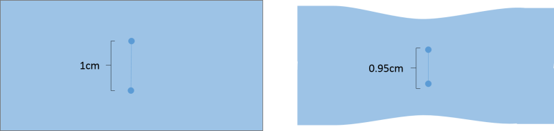
In a simple example what I would like to do is be able to take two nodes in a 2D plane let’s say 1cm apart initially. Then prescribe for the first load step that now the two nodes must be 0.95 cm apart, as a result the structure around this two nodes would deflect. Basically instead of applying loads I am applying displacement constraints. The constraint equation for this example would look like:

0.95 = sqrt( (N1x-N2x)^2 + (N1y-N2y)^2 )

The common quick response I get to this is just use displacement BCs. But I don’t know where the two nodes will be (that is what I am solving for), all I know is their initial location (and therefore distance between them) and there final distance between them.

Ultimately I want to do this for more than two nodes and on a larger scale, but I don’t want to muddy the waters. If I can get this simple example to work I will be set after a little scripting.
 
Replies continue below

Recommended for you

I have not worked with those so I may be missing something. I have been looking into the dependent amplitude definition this morning. I can apply that to displacement BC but this is still for the displacement in the global system, not the displacement relative to another node, which will also move.

Below is an image of a simple example, I need to be able to directly control the displacement/strain between the two nodes. For instance I have thought that I could simple connect the two node of interest with a truss element, then if I could specify to truss element to strain X amount I would be business. But as yet I have not been able to find a 2D line element that I prescribe the strain of. Certainly I could use disp-BC to tell the ends where to go, but that does not solve the problem.

I could use a truss element with expansion then change the "temperature" except this does not give direct control of strain. The resulting strain would be a function of the delta T and the stiffness of the "truss" material and the stiffness of the surrounding material.

I am aware this example could easily be solved the symmetry, the end goal is not so simple so that won't work.


Picture1_klmjmp.png
 
Couple of options come to mind:

You could use a connector element between the two nodes with a nonlinear force-displacement behavior assigned to it. And then, apply a specific amount of force to get the specific displacement you desire.

Another option might be to look at subroutines (UDISP). But if you haven't used subroutines before, I wouldn't recommend it; it can be a pain to just get everything up and running with them.

*********************************************************
Are you new to this forum? If so, please read these FAQs:

 
Got it thanks.

I went with your first option, which still had the same problem, if I assign a force the resulting displacement/strain is a function of the force the the structure around the connector. Example I would not get the same strain if the connector was in rubber vs steel. But I discovered I could use a "Connector Displacement" BC to enforce the displacment.

I took the line which I wanted to be the extending actuator partitioned into equally spaced units and then created many connectors. The connectors are basic transnational only connectors. I did not define any properties like elasticity to them, they simple exist. Then apply the BC and voila. The case shown below is a simple line but I can make curved lines and still only have to input x.x displacement of the connector and due its definition I get the desired behavior.

Now my question is how do I determine how much force it is taking to enforce the "Connector Displacement" BC.

Picture1_gv8f0i.png
 
Sort of found my own answer FieldOuput>>Connector>>CTF

But when I blot the whole model goes gray. The color scale gives a range which seems okay for the force, but I don't have any way to visualize it because the connectors have zero area and can't be rendered like beam and shell elements. I can plot the values of force in the XY plotter, and it tells me the element number and the value. But I would have to go back and looked up each elements location to make sense of the data.

Thoughts?
 
Thanks, again it was a combination of things. I got the correct output, the trick to visualizing was:
ODB Display Options>>Entity Display>>Show Constraints.

 
Status
Not open for further replies.

Part and Inventory Search

Sponsor