Continue to Site

Eng-Tips is the largest engineering community on the Internet

Intelligent Work Forums for Engineering Professionals

  • Congratulations cowski on being selected by the Eng-Tips community for having the most helpful posts in the forums last week. Way to Go!

Coding by finite element method a truss

Status
Not open for further replies.

Amine A

Mechanical
May 9, 2020
80
Hello,
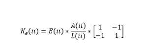
I am coding the truss problem by finite element (figure below).I found difficulties at the level of the assembly of the stiffness matrices . Since the beams do not have the same materials, we will not have the same stiffness matrices. In the program , how to do the loop of assembly ? Any ideas please ?
 
 https://files.engineering.com/getfile.aspx?folder=b055406c-9bfb-4e99-b6e9-d82135888e5a&file=poutre.JPG
Replies continue below

Recommended for you

why should different material create problems ? E is just one property of the truss member stiffness (L/EA) ...
each element has L/EA as a stiffness
then at each node assemble the member stiffness in global co-ords

suggest you start with a very simple one first, one you can hand calc.

another day in paradise, or is paradise one day closer ?
 
Element (ii) stiffness in local coordinates is given by
image_usete9.png


You need to transform the element stiffnesses from local coordinates to global and then assemble in global stiffness matrix K.

E(ii)= Element Young's modulus
A(ii)=element area
L(ii)=element length
 
rb1957 , goutam_freelance : Thank you for the replies. Here as you can see I have 17 beams and each beam has it's matrix, so my problem is : how should write each matrix as they are different , I can't use iteration so should I write each 17 lines for each Ke of a single beam ??!!!!
PS: goutam_freelance , I won't neglevt flexion in this example, so the matrix still like the one you showed me ?
 
ok, start with a simple example. You can model beams (with bending), just more complicated (axial and bending stiffness, two internal loads).

you are asking very basic questions, so get some texts ... there are plenty on-line.

you assemble the global matrix from the grids/nodes/points.

another day in paradise, or is paradise one day closer ?
 
Thank you. I saw some examples and I did simple problems. If you see the picture of my problem you will notice that it's not the same thing , as we don't have same materials , same angle of the beams ... We will have different stiffness matrix that's why I'm asking
 
It shouldn’t be a problem to loop through all elements, create their local stiffness matrices and assemble them into global stiffness matrix. Which programming language do you use ?
 
That's my problem... It's in the creation of the Ke and the assemly .... It's not similar... I'm using python
 
if you can build a simple truss, then you should be able to do a more complicated truss. each truss element has it's own stiffness matrix (in local co-ordinates). assembling into the global matrix is "just" combining the elements based on which nodes they affect and what angle between the local axis and the global axis.

different material is "only" an impact to local stiffness.

another day in paradise, or is paradise one day closer ?
 
or anything in between ...

another day in paradise, or is paradise one day closer ?
 
Amine A said:
That's my problem... It's in the creation of the Ke and the assemly .... It's not similar... I'm using python

Once you have seen and understood the basic procedure for combining the beam matrices into a global stiffness matrix your question will be answered, including why the beams having different lengths, angles and material properties is not a problem.

Regardless of the language you intend using in the end, I suggest setting up a simple problem on a spreadsheet and getting that to work.

The link below has links to a series of blog posts that work through that exercise, ending up with VBA and compiled code. The 3rd post addresses your question in this thread, but it is worth looking at the first two as well.


Doug Jenkins
Interactive Design Services
 
Hello,
Can you please tell me what is the size of stifness matrix of an inclined element if we consider traction , compression and flexion ? is it 4*4 or 6*6 ?
I have never saw a truss considering flexion problem....
 

I assume when you use the term "truss", you are using the standard interpretation that all members carry axial forces only, no shear forces or moments; hence node displacements are translations only, no rotations. (2 DOF per node in a 2D model, 3 DOF per node for a 3D model)

"Frame" members can carry axial forces, shear force, and bending moments, and node displacements include translations and rotations. (3 DOF per node in a 2D model, 6 DOF per node for a 3D model)

Hence a 2D truss element has a 4x4 element stiffness matrix; while a 3D frame element has a 12x12 element stiffness matrix.


The clearest way to understand how to form the global stiffness matrix is to consider the freedoms at each node, and how they interact. For your example, and ignoring bending moments, each node has two freedoms, deflection in the x and y direction.

There are 6 unrestrained nodes, so you need to find the magnitude of 12 deflections, so your stiffness matrix will be 12 x 12.

Numbering the freedoms in alphabetical order you will have 1,2 at Node E through to 11,12 at Node J. Each freedom number represents a row and column in the stiffness matrix, so for instance row and column 1 and 2 will combine the stiffness values from end 2 of elements AE and BE and End 1 of EF and EH.

If you want to include bending moments (assuming the nodes are fixed rather than hinged) there will be an additional freedom at each node, so your stiffness matrix will be 18 x 18.

Doug Jenkins
Interactive Design Services
 
Yes , the problem is that in the exercice he didn't specify this... He said a structure composed of beams ( the figure I showed you on the first comment) and we will consider traction , compression and flexion. So I don't know with which case I will work based on that statement
 
Yes , thank you, so if I include bending...each local (for an element of 2 nodes) stifness matrix will be 6*6 no ?
 
Status
Not open for further replies.

Part and Inventory Search

Sponsor