Continue to Site

Eng-Tips is the largest engineering community on the Internet

Intelligent Work Forums for Engineering Professionals

  • Congratulations cowski on being selected by the Eng-Tips community for having the most helpful posts in the forums last week. Way to Go!

CLT floor lap connections

Status
Not open for further replies.

Agent666

Structural
Jul 2, 2008
3,080
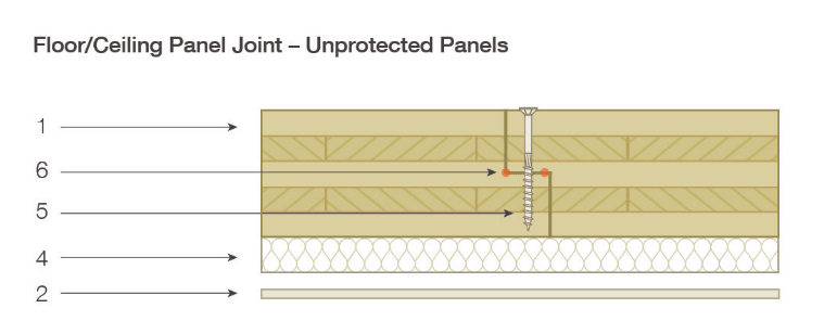
After some advice on CLT floor connections between floor panels under diaphragm actions (transferring shear along joints).

I'm finding from a strength perspective we need fixings in joints at very close centres, we can work out the capacity of a screw at minimum spacing, but at some point it seems intuative that the half timber tongue must become a limitation on the capacity that can be transferred in these types of configurations, wondering if anyone has come across any guidance on this.
image_wvo2jn.png


I've read a lot of advice on CLT joints, but no one seems to recognise this in any design procedures, albeit most of the examples I've seen have relatively wide spacing to the fixings like 200-300mm. Generally it is work out screw capacity, and screw capacity is independent of spacing and potential brittle failures of the connected timber.

But if the fixings are at minimum spacing, say 50-100mm , and you're finding you need multiple rows to achieve the capacity, then does the timber left at the half joint become critical at some point, and if so how to assess?

A few texts mention in passing being aware of splitting when you have close fixings, but that seems to be the grand sum of the advice.

Anyone aware of anything in this space?


Replies continue below

Recommended for you

I've always thought these little laps were lacking. Why not lap the sheets ~ 200 mm or more, and use at least two rows of fasteners?
 
Not seen much in the way of advice related to that either to be honest. Seems like vertical load wanting to transfer across the joint will become more prominent so the notch may have to be reinforced.

Another thing is there is no glue between the vertical lamination joints. So 200mm wide joint may have an entire width of wood exposed without any tying back into the perpendicular laminations if you know what I mean.


Agent666:
Use a longer screw, and have the screw head at about 1:30 (o’clock) and the point at about 7:30, that’s 40-45° from vert., with the screw axis going through the left red dot at your #6. That should engage more wood, and more meaty wood, from the splitting standpoint. I’m not quite sure what the meatiness factor is though. I’d put a line of glue down the joint to improve its shear flow cap’y.
 
That's the thing though, you make one side meatier by putting in off centre at an angle, but not the other. If I'm following you in offsetting to go through point 6 means the top tongue is almost engaged less.

Or are you saying do this from both top and bottom sides?

 
Agent666:
It might be better if that joint were a tongue-n-groove at the middle ply, and I think I’ve seen that. To make the tongue or lap much longer probably leads to breakage of the tongue during handling and installation. My thought was…, assuming your lap joint is 2” long, your screw is about 1” right of the top vert. joint. The head of my screw would be 2.5” +/- right of the top vert. joint; the screw would go through the left red dot #6, and the tip of the screw would be 2 or 2.5” left of the top vert. joint, approx. 40-45° from vert.,. The tip of the screw is well engaged. The head of the screw and its length engages more of the upper lap (better edge dist.) and is nearer the full thk. part of the panel. This should reduce the chance of splitting and engages more wood, but off the top of my head, I don’t know how to put numbers on this. Yes, if accessible, you could do this from above and below, but not in your sketch with the insul. and all. If acceptable by code or the AHJ, glue is so effective in this application because of the way it distributes the shear flow into a low shear stress in lbs./sq.in., and the screws do a good job of clamping the glue joint.
 
i would think placement/erection would be difficult with a toungue and groove panel, especially if the toungue and groove have a tight fit?

I can imagine the difficulty in trying to get the toungue into the groove when working off of a crane placing the panel
 
Usually from what I've seen in overseas literature they place down the units and bring together by hand with special clamps to really pull them together with no gaps. Then fire screws into the units. I'd imagine they must allow for some minor tolerance on the tongue thickness to allow it to go together easy enough and not hold up units following.

 
The last CLT project I was at they used steel plate and lags to resolve the shear forces between units. In that case they have a topping. A year or two ago we worked on a net zero project where they imported some hollow wood box sections from EU. I believe they connected adjacent units with screws, but that was a small floor. I am not the EOR for either projects, so I did not pay close attention to the details.
 
On the CLT project I worked on, they used plywood splines that were screwed into each adjacent panel. Our project had a concrete topping so top side visuals were not important. They router out a depression in the panel at the edges to allow the top of plywood spline to match top of CLT.
 
Status
Not open for further replies.

Part and Inventory Search

Sponsor