MRSSPOCK
Mechanical
- Aug 29, 2010
- 303
Could someone please give me an idea what is going on with this board design.
The board is from an old coffee machine.
The optical sensor is used to detect the presence of a linear ram.
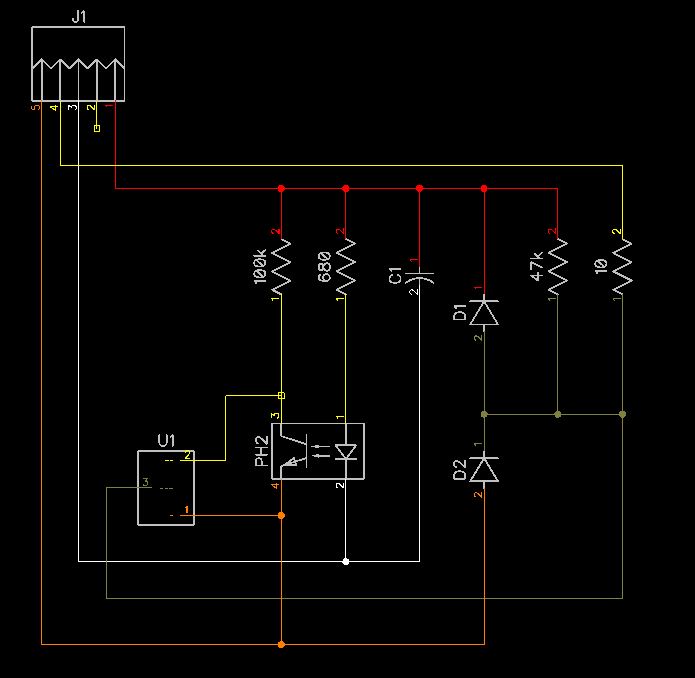
I am just trying to understand the circuit, and figure out what that 3 pin black component is.
Can anyone give me some clues please.
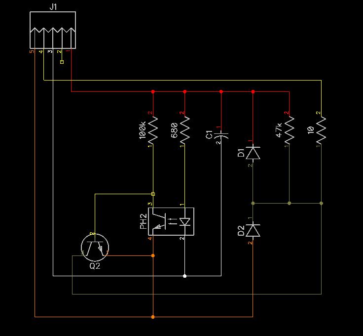
I don't have access to the machine at the minute, but I do know tha pin 1 is 12V with respect to pin 3.
Here is the circuit diagram as I see it, and a photo of the actual board, with a couple of scribbles showing the optical sensor orientaion.
Is there a way to determine what diodes they are?
I get the 680 ohm resistor for the LED and the decoupling capacitor, but that's all.
Thanks
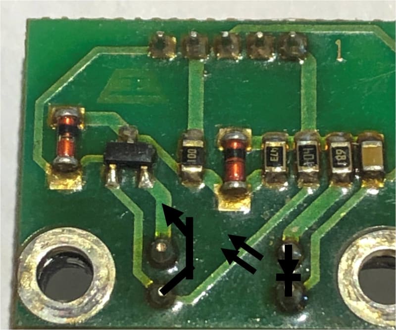
The board is from an old coffee machine.
The optical sensor is used to detect the presence of a linear ram.
I am just trying to understand the circuit, and figure out what that 3 pin black component is.
Can anyone give me some clues please.
I don't have access to the machine at the minute, but I do know tha pin 1 is 12V with respect to pin 3.
Here is the circuit diagram as I see it, and a photo of the actual board, with a couple of scribbles showing the optical sensor orientaion.
Is there a way to determine what diodes they are?
I get the 680 ohm resistor for the LED and the decoupling capacitor, but that's all.
Thanks